Okay, if you’re following along, you know the drill by now. If not, check back in the beginning of the first post for the explanation.
No commentary this time. You’re on your own. Enjoy!
Regards,
Mike
What do you see? Addendum
October 3, 2011
From the comments section, you can see a great conversation has developed. I wanted to post a couple more photos to illustrate what we’re talking about.
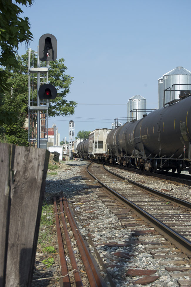
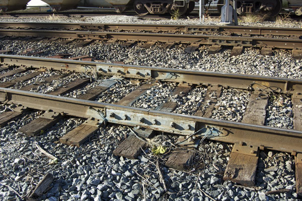
Photo 1.1 below shows the two gray colored spots from the main photo close up. It’s a pair of bonded rail joints for the siding and signaling. You can see all the wiring involved as well as other debris scattered about. A factory weld for joining two pieces of rail is visible on the uppermost rail just under the hopper car truck towards the upper right corner of the photo.
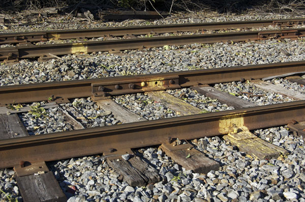
I mentioned clearance points in reply to one of Matt’s comments and the reason is shown below on the yard tracks near the depot. These began showing up on all sidings and spur tracks a couple of years ago. I don’t know if this is just Norfolk Southern practice or something recently mandated by the FRA.
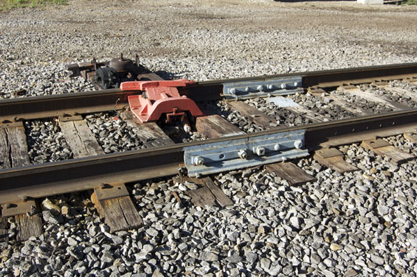
 A different color is used to highlight other hazards like this derail where the yard lead comes off the main line. As Matt pointed out in his comments, prototype track is loaded with details like these, that we usually overlook in the rush to get something done.
Mike


Looks like they just upgraded the siding to continuous welded rail. Wonder how I can make a tie plate with a chip out of it like the one in the foreground. Even see the old time rail anchors with their end piece sticking above the base of the rail, must have reused them. Lots of pieces of wood lying around, may be the remains of wood place in old spike holes when respiking.
Like the ties end in the ground to the left as well, serving as a stop for a road or parking area?
Best thing is the little green bottle..how to model that!
Hi Matt,
Good eye! You spotted details I haven’t even noticed. Yes, the upright ties do block an unused crossing. I used a slight telephoto lens, so there is some distortion to the shot.
The siding was recently relaid, as was all the track in town. Did you notice the clearance spots painted on the siding rails?
Why not nip off the corner of a tieplate for a broken one? the old soda bottle could be done from styrene rod with the end filed down a bit.
Regards,
Mike
Mike,
You know, had not thought about clearance spots. I was thinking you were standing next to a long siding and that the two spots in question were field weld spots. Always thought that modern modelers have the advantage of continuously welded rail which can also have breaks represents by field welds. Since those “mini-blast furnace” as I called them left a flash all around, even on the rail head, that was ground down with a grinder.
One think we all miss is the “OTM” (on track misc) of spikes, plates, rail bars bolts etc as well as the assorted “stuff” that falls off of open loads, whether it is coal on a curve or banding from lumber loads that has snapped and fallen off.
Well, I can’t beat Matt’s eyes – Can I ask where the location is Mike?
It looks familiar to me (which probably means that I haven’t set foot within one thousand miles of it).
Hi guys,
This conversation is great. Your comments help me see things with fresh eyes. Matt, the comment about field welded rail joints got my curiosity up and I went back to take another look. The spots in question are a pair of bonded rail joints. I mentioned clearance spots because a few years ago, patches of paint started appearing on sidings and spur tracks in town. The weather has done its work on them, since the paint used to be very distinctive and easily seen. As you noted Matt, there is a lot of little details like these that we usually don’t pay much attention to.
Regards,
Mike
Pete,
It’s Richmond, Indiana. Have you come close?
Mike
Mike,
I looked for a photograph of a field welded rail joint, but could not find one. I remember them clearly though since at the time I thought that would be a great idea for an electrical block(this was in the pre-DCC era). A piece of styrene glued in could represent the final results with just the rail head flush and the rest left “as is”.
Thanks for the new photos! On your new pictures, notice all the copper wires running around the joint. I have never understood 12″=1′ electrical work, but it must have something to do with signals or track control. I notice that almost every mainline rail joint has several cooper wires running around a joint. Wish I could solder a small piece of copper around joints as well.
I am not sure why NS has painted the joint bars, but it does make those copper wires stand out. On older track with bars, you may note 4 hole bars vs the more modern 6 hole joint bars. Not sure when the Class one’s made the switch, but the secondary lines/ house tracks, etc. seem to have stayed with 4 hole joint bars.
Matt
Hi Matt,
Strangely enough, prototype signaling is a lot like our model wiring in that the track is divided into electrical blocks of sorts. I’ve noticed many rail joints are insulated in some manner. I presume that train or circuit detection is in play somehow. All too arcane for me!
Four versus six hole joint bars are determined more by rail size and weight. Above a certain rail weight six hole bars are used. My branch has 75-100lb. rail for most of its length with four hole joint bars throughout.
Regards,
Mike
Not within 750 miles, Mike!!!
In the UK they have taken to painting sensitive parts of rail with white paint – complex point systems and the like. Apparently, despite the mild climate (to put it kindly) of the UK this is to ameliorate daytime temperature fluctuations due to the Sun. I know about “Rail neutral Temperature” when track is laid i.e. it is usually heated to a pre-determined temperature based on the geographical location.
I have not seen this in the ‘States – does it happen (the painting I mean)?
Best, Pete.
Hi Pete,
I simply don’t know. Perhaps someone who does will weigh in on the subject at some point.
Regards,
Mike