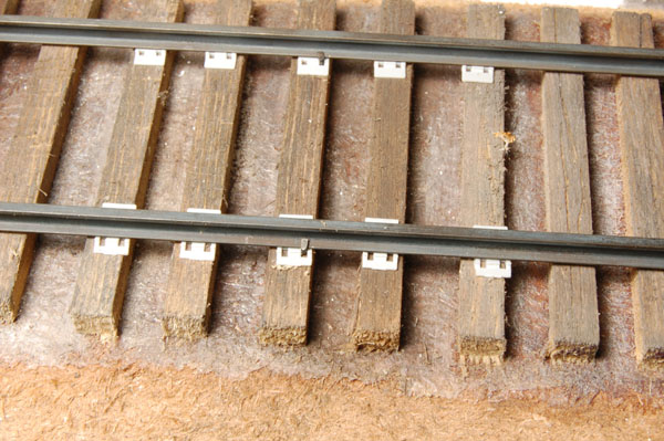
Tieplates are rather simple. The problem is you need them in large quantities. Let’s do the math: 48 scale feet of track (12 real inches) with ties spaced every 21″ results in about 27 ties per actual foot. Twenty-seven ties require 54 tieplates. Grandt Line plastic tieplates are sold 100 for $3.50, or 3.5 cents each. Right O’ Way plastic tieplates are 200 for $5.50, or 2.75 cents each. Old Pullman Model Railroads offers tieplates in quantities of 1000 for $32, or 3.2 cents each. You can see how tieplates can become a very expensive detail to add to track. Of course, you can cut your own from styrene. A ten-strip pack of 0.020″ x 0.156″ styrene will yield 560 tieplates for about $3 or 0.5 cents each.** While inexpensive, they will lack the nice detailing of the others. Tieplates can also be laser cut from cardboard, or styrene, and also photo etched from thin metal. As of this writing some of these are in development but not yet commercially available. If you happen to be using commercial flextrack in any scale, the tieplate detail in usually molded into the ties. For those working in HO Scale, tieplates are available from the P87 Stores [www.Proto87.com]
Laying rail at last
This was the first time I used individual tieplates in handlaying track, and I freely admit that they do require a degree of patience to work with. They probably won’t be everyone’s cup of tea regardless of how much the track is enhanced in appearance. However, with a bit of forethought, the job can be less stressful. It is tempting to just place a bunch of tieplates, lay a piece of rail on top and start spiking away. I quickly found that the loose tieplates would go everywhere, especially down between the ties, where they are fun to retrieve. I’ve learned that in the past, lots of people glued the tieplates in place before laying rail. That never once dawned on me, and in this case, ignorance was truly bliss. How would you correct any errors in alignment of the rails or gauge if the tieplates are glued down?
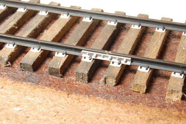
What worked for me was to place five or so tieplates under each rail and spike the one in the middle (photo above). This secured the rail enough to hold the others in place, yet allowed me to place a few more tieplates along the track’s length. I placed spikes every third or fourth tie just as you would normally, and added tieplates as I moved down the length of rail. I used a heavy metal track gage that sits on the rails, which allows me to lay both rails at once. The nice thing about my gage is that it is the same width as the ties. I can just line it up with the tie ends and know the rails are centered on the ties.
Sprue cutters make easy work of cutting the tieplates from their sprues. I simply pinch three or four between my fingers as shown, and nip away. This keeps them from flying off everywhere. As I add plates and spike the rails, I also check the rail’s alignment to be certain it isn’t getting too wavy. Sometimes I had to make adjustments where the gauge was off. I used a wide bladed screwdriver placed near the base of the offending rail, and tapped it gently with a small hammer to nudge things into alignment. Any serious errors may need to be taken up and redone. Once a length of rail is partially spiked in place, I can continue laying rail or go back and fill in the remaining spikes. Typically, I filled in the remaining spikes until a rail was solidly in place, and then moved on to the next section. I like to see some finished effect right away, so doing it this way was a personal choice. It also cut what could be a mind-numbing chore into manageable chunks. You can do what pleases you.
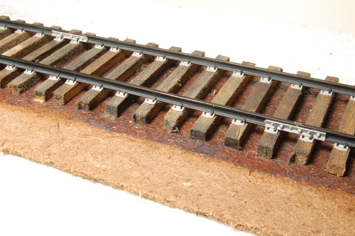
In addition to four spikes per tie, I also added joint bars every 39-scale feet at this time (above). Prototype practice will offset the spacing of them on the opposite rails for a smoother ride. An offset of ten ties is typical, though this can vary (photo below). One thing to be aware of is any spikes in the ties under the bars will have to be removed for them to seat properly. I had to do this numerous times, because I didn’t add the joint bars until after a stretch of track was down, however it was a fairly simple task to pull the spikes and slip in the joint bars.
You’ll notice in the photos that I didn’t bother to pre-paint the tieplates or joint bars. I felt that they would get scratched in the spiking process and have to be touched up afterwards. Therefore, I left them unpainted until I was ready to weather the track.
Turnouts
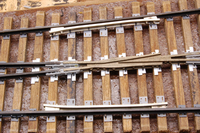
Prototype turnouts have a host of special hardware and tieplates that perform specific functions. Under the points are long tieplates called slide plates. These allow the points to slide back and forth, while protecting the cross ties from abrasion and wear. Longer tieplates are also used where the closure and running rails are too close together to permit using regular tieplates. The frog and guardrails are also areas of special interest. Offset tieplates or hook tieplates are used here to help spread the load of the frog casting and forces of passing trains. In the photo below, I used commercial plates from Right-O-Way under the guard rails and scratchbuilt the offset plates under the frog from 0.020″ x 0.080″ styrene. Our book, Detailing Track has more information about these special tieplates in Chapter Five.
While there are some standards from the ARA and individual railroad company engineering departments for placement of these plates, field conditions will often vary considerably. Reasons include older track that hasn’t been upgraded yet; track from a merged line that has different standards and many others. The bottom line is that prototype track can vary widely in appearance. It isn’t as uniform as we often model it. Questions or comments anyone?
Regards,
Mike
** Update 2021 Please be aware the prices in this post are hopelessly out of date. I left the breakdown in place to show how quickly costs in this scale can add up.


Of course, on the flipside is my story, where I was using individual tie plates from P87 stores in HO. I figured that the switch to P48 was going to save me money because I would be using fewer of them per foot, but it is true that laying track this way can cost quite a bit.
Depending on where we modeling, the degree of uniformity will, as you say, vary wildly. Of particular interest are the tieplates, not so much on a mainline, but perhaps on secondary trackage near to a mainline. Take for instance the yard in Mansfield, MA, on the Framingham Secondary of CSX, immediately adjacent to Amtrak’s Northeast Corridor. Mansfield is of note because presently it is one of two places in the US where trains are rated to go the fastest. The track is rated at 150mph and the Acela can and does hit that mark every day. Take this from a guy who through the course of his work with CSX as a freight conductor once found himself on the track in front of an Acela. 1000 ft isn’t very much when the train is going 150 mph (4 seconds to be exact.) Anyway, even on the corridor, with it’s concrete ties, there is variation. Depending on the manufacturer of the ties, there are at least two different tieplate variations. When you walk around in Mansfield yard, (I wouldn’t do that unless I worked for the RR) you see where tieplates needed to be replaced and were replaced with used tieplates from the mainline instead of new ones for lighter rail. So as you walk along you can see variation from one tie to the next to the next. Even on a mainline, the ties are not perfectly in line.
The problem is that this type of variation requires close examination to see. What I mean by that is that if we are trackside, we probably won’t see it. We will if we get close to the tracks and look, but that isn’t really advisable. It is readily apparent from say an overpass, which coincidentally is basically the same vantage point that we view our models from, particularly in O. So to say that this isn’t noticeable on a model (it probably wouldn’t be in N-scale, that’s true) is poppycock. In fact it is readily noticeable in O, because of the distance and vantage point that we have with our models.
If we spend all of our time working on a beautiful rendition of a particular loco, in my view we are doing the rest of our modeling a disservice if we just plop it down on dinky dink trackwork, but that’s just my opinion of course.
“If we spend all of our time working on a beautiful rendition of a particular loco, in my view we are doing the rest of our modeling a disservice if we just plop it down on dinky dink trackwork, but that’s just my opinion of course. ”
It’s an opinion I share Jim. I’ve mentioned many times that my layout is 54″ or so high, about my standing chest level. The details of the track are very plain to see at this height, so I tried to pay close attention to how they were modeled. Such variations as you mentioned would also be plain to see. All one has to do is look with an open mind instead of preconceived ideas. Learning to “see” something accurately isn’t reserved for just scenery as in my other post. It’s relevant regardless of the subject, whether it be accurate track, freight cars, locomotives, structures or anything else. It’s all related.
If a modeler deliberately chooses to ignore these things, then that’s their freedom of choice in action. However, the rewards of paying attention are substantial and they’re missing out on a lot of satisfaction that comes from a depth of experience rather than just skimming the surface. That’s just my opinion of course. Thanks for commenting.
Regards,
Mike
Excellent post Mike. Worked for a scrap company that scrapped abandoned railroads or picked up sectional rail when ribbon rail was laid back in high school and college. Always thought to myself that modeling the track gives the sense to the viewer that you are in the scene. Spikes, plates, even the wooden sticks used to fill spike holes when respiking all add a degree of interest to the track level part of the scene. Those out of use house tracks with the broken rail or even a piece of the rail head splitting off tells the viewer, “they don’t use that one anymore!”
Having moved from those dreams of monster layouts to more of a narrow shelf and just a several switching locations has made me think about everything close up, the details, even the track are important to set the scene.
Hi Matt,
Yes, it all adds up to make a convincing scene. Modelers tend to focus on a narrow range of details and our efforts can suffer as a result. Interesting insights. I didn’t realize that they plugged old spike holes with wood sticks. Makes sense though. Glad to have you with us, thanks for the comments.
Regards,
Mike
Great Looking Track! I’d love to see that gauge. I’d like to start laying my own ties and tie plates but have been struggling to figure out how I will keep them in gauge. My current plan is to lay one side, then use a guage to lay the other, but I’m afraid I might not lay the first side in the right place. The gauge you mentioned sounds like a great idea.
As for not painting the tie-plates before hand I think it’s a good idea. I’ve been working with Proto87 tie plates and tried to pre-weather them. Doing so makes it very difficult to determine the proper orientation for setting them down. Because of the weathering, I couldn’t tell what was side was up and which was down.
Hi Greg,
I can’t believe I didn’t include a photo of the gauge in the post. Go to the Masterclass Modeling tab in the menu and scroll down to the last photo of the open book for a look at the gauge.
You could make one if you have a milling machine and the know-how to use it. Lacking that, cut some saw kerfs to the right gauge in a block of hardwood cut to the same width as your cross ties. Having the gauge the same as the ties makes it easy to center the rails.
I can’t even imagine working with individual HO tieplates! Painting the quarter-inch scale plates isn’t that hard. I do it when I paint the rail sides using a small brush.
Regards,
Mike