Scratchbuilding is 99% problem solving, especially when working with unfamiliar materials. You’re learning the characteristics of a material such as plastic or brass and how to successfully work with it. At the same time, you’re working out the best techniques and construction sequence for the model. Learning from multiple failures is time well spent not wasted.
The corner posts of a covered hopper are a key part of the end cages. They support a number of other pieces like the grab irons as well as defining the look of the car. On a full-sized car, they generally offer a delicate profile that contrasts with the mass of the car body. Done right on a model, they lift the quality of a build and add a high degree of realism.
For my Pullman Standard grain car, the corner posts are a simple L shaped steel angle that is roughly four inches wide on each flange and a quarter to three eighths of an inch thick. Making these to scale from flat stock is easy with simple tools like seaming pliers or a bending brake. I just layout a strip that is twice the width of the finished angle, mark the centerline, then line up the tool on that line and make the bend. For short sections like this, the seaming pliers make quick and easy work with practice. Longer lengths are made on the bending brake. With care, I can make flanges as small as 0.040” although that is pushing the practical limits of the precision this basic tool offers.
Bending the posts is the easy part. Next comes the fun of laying out the hole pattern on both flanges for the grab irons along with a row of six rivets on both flanges at the top of each post.
Rivets
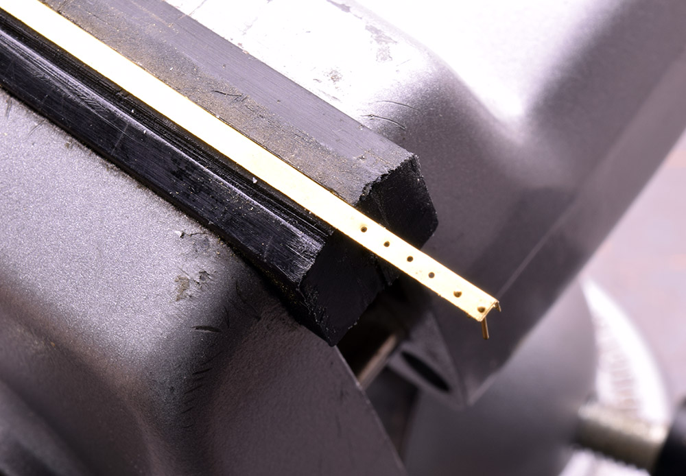
Once they are folded, the post flanges are too narrow for the dies of my Northwest Shortline Riveter. I could press the rivets before folding the angle to shape but the bending process will likely crush them on one or both sides. Given these factors, I initially decided to use plastic rivets from Tichy. However, after receiving a few samples of brass rivets from Scale Hardware, thanks to Mike Lytle, I’m going with them.
I was aware of this product from reading many build threads on the Westlake Modelers Forum. With these builds mostly in scales like 1:20.3, I assumed the Scale Hardware products were too big for quarter-inch scale. I was wrong about that. Seeing the brass rivets first hand proved eye opening. They’re beautiful and come in a wide range of sizes that provide a crisp and neat appearance on the model.


(Top photo.) In the last two holes on the far right, these 0.6mm brass rivets from Scale Hardware (part #RT-06) are precise, crisp and clean. The head measures 0.0236″ and compares favorably in size to 0.020″ plastic rivets from Tichy that I initially planned to use. (Photo above.)
Layout
Laying out the pattern for the rivets and grab irons is important. The spacing for both has to be spot on or the model will suffer. Several years ago, I came up with the idea for a jig and spacers that make drilling the holes in the posts straightforward and easy. At the end of this post there’s a link that describes the jig and process thoroughly.
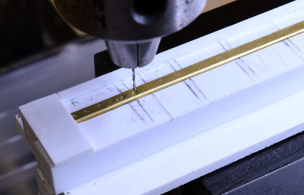
My first thought was to reuse the older jig and make new spacers. That would have worked but the new corner posts are made from thinner stock and fit too loosely in the slot of the original jig. Shimming the post in place helped but there was still enough slop to throw one or two of the holes off from the rest. The solution was making a new jig with a slot that fit the 0.005” sheet stock of the new corner posts.
In the photo below the jig is set up on the Sherline mill for it’s greater precision over my aging drill press. I made a few practice pieces to refine the process and find any potential errors before committing to the final pieces. Again, I consider this time well invested. Once the corner posts are ready, I need to figure out a way to hold and solder the grab irons on two sides of a post for each end of the car. I confess I’ve been procrastinating on that one.

A new jig to hold 0.005″ thick angle stock in place. Like the previous fixture it’s made of 0.250″ square styrene strip and 0.40″ sheet. Two sets of custom spacers (not shown) make drilling the holes for grab irons and the rivets (seen here) a simple matter on this practice piece. See the link below for a complete description of the process.
Regards,
Mike
Links
Please note these are not affiliate links. I receive nothing in return for posting them. They’re included for your benefit.
Drilling Jig
This post describes the construction and process of a jig for drilling neatly aligned, consistently spaced holes. The basic jig can be customized in any number of ways.
Scale Hardware
Now part of Model Motorcars LLC, this link will take you to the Scale Hardware section of their website. Scroll way down this page to find the rivets, or simply use the category selection box in the upper right and choose rivets.
PS4427 Reference Article in the AC&Y Historical Society Newsletter
This PDF article features a number of high resolution photos that hold their detail when enlarged. Along with the plans in my 1966 Car Builders’ Cyclopedia I’m using it as my main reference source.
0 Comments