Rebuilding the end cages on the AtlasO Trinity covered hopper is a daunting task. Each assembly has vertical posts that need to have precisely located holes drilled in them, a process that leaves plenty of room for mistakes. I’ve spent a lot of time over the past weeks staring at the model, studying photos, making notes and staring at the model some more. I assure you, this is not wasted time daydreaming. It’s critical to my understanding of the work to come.
Each end cage has six vertical posts and the most intimidating task is locating and drilling a series of #78 holes (.016″) in every one. Two of the 3/32” brass angles I’m using for the corner posts requires up to eleven holes that need to be aligned on two sides in a specific right and left hand pattern. Few things look worse on a car than misaligned grab irons, so my drill press and a jig of some kind are crucial.
A good beginning but I can do better.
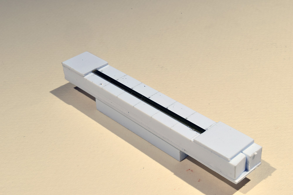
The jig has two 0.250″ square styrene pieces that form a slot to hold the angle for drilling. Scribed witness marks indicate the rung spacing, while the 0.040″stops keep the angle from sliding around. The 0.250″ pieces underneath rest on the bed of the vise and allow the jig to be clamped securely.
My first jig was a complete failure. While it held the work piece steady, it was impossible to see and align the drill bit. I needed more thinking time, so I moved on to another part of the project.
A few days later I took a different approach with the jig seen above. As you can see, one flange of the angle fits into a slot and is held in place by stops on each end. The slot is a snug fit and the angle stays put nicely. I also made some witness marks on the jig equal to the grab iron spacing. The jig clamps into the vise on the X-Y table of the drill press and I manually line up the bit on each mark, drill the hole and advance the table to the next one. After drilling the holes on one side, I rotate the work piece and put the other flange in the slot to drill the holes on the opposite face. It sounds more complicated than it actually is.
The new jig worked well but there were still problems. Manually advancing the X-Y table for each hole introduced errors in the spacing and alignment. I was on track with the overall design but needed a more precise way to position the work piece for each set of holes. I wanted a way to advance the piece without moving the X-Y table. The solution was simpler than I imagined.
A series of graduated spacer sticks is the key to success.
Count To Six With Spacer Sticks
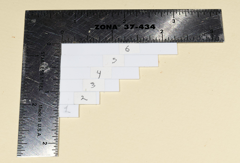
The next evening, I made a second, larger version of the jig. This one has a longer slot and only one stop at the end. The extended slot allows the corner post to slide down the jig at least twice its own length. To consistently index the post for drilling the holes, I made a series of spacer sticks. Each spacer is longer than the previous one by an increment that equals the spacing between each grab iron. Using each spacer sequentially moves the corner post the distance of one step.
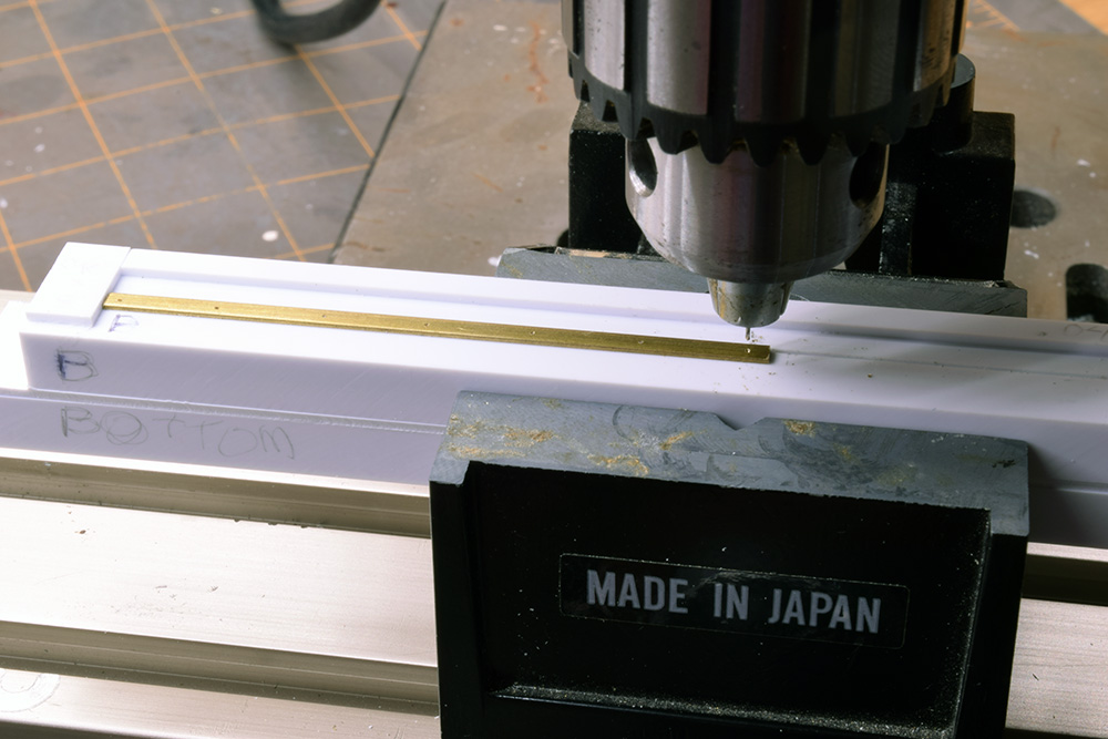
To start, the corner post is positioned tight against the built-in stop and I drill the first hole at the opposite end. Then I slide the post away from the stop and insert the first spacer (photo below). I make certain the spacer and post are both tight to the built-in stop and drill the second hole. Please note the post in these photos has already been drilled. I’m recreating the process for the sake of illustration.

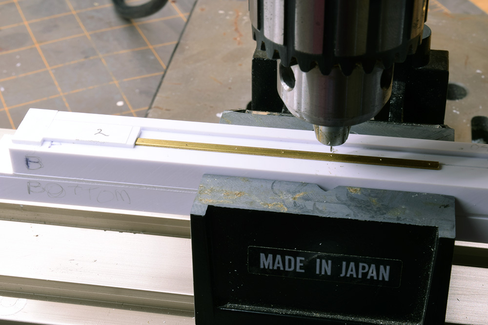
(Below) For the tall ladders I repeat the process with each progressively longer spacer until I reach the end of the corner post (I think you get the idea so spacers three through five aren’t shown). The short ladders on the other corners need just four holes, so I only use the spacers for that number of holes.

The last stick locates the final hole for the tall ladder on this side of the post. Once finished with the first side, I rotate the corner post and place the flange I just drilled in the slot. Keeping the orientation of the post and pattern of holes in mind, I repeat the process and drill the opposite face. Because the second flange faces the opposite direction and is now on the other side of the slot, I have to move the table forward or backward to center the holes on this face. That’s the only manual adjustment to the X-Y table in the entire process.
The new jig works like a charm. The spacers provide the accuracy I want and the holes are perfectly aligned on both sides of the corner post. Since each vertical post of the end cages line up at the bottom, I can use the jig and spacers to locate and drill the holes for each one. The only thing is to be aware of the right/left orientation of the posts and the pattern of holes when placing a piece in the jig.
I’m extremely satisfied with the results the jig produces. I took care to label and number the spacers and everything goes in a plastic bag with a set of instructions so I can quickly refresh my memory when using the jig in the future. This aspect of the build intimidated me the most and I’m delighted to have it turn out well. The next major hurdle will be assembling all these delicate parts. I sense another jig (or two) coming.
Mike
0 Comments