The first step is to see the work as it is.
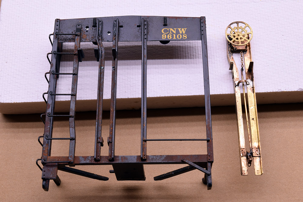
I’ve rebuilt the brake assembly and feel it’s a better outcome. Taking Mike Lytle’s comments from the previous post to heart and learning a few lessons from the original version, I made some changes and also built a new assembly/soldering jig.
Keep Striving For Quality
The new uprights are made from 0.008” shim stock instead of 0.005”. The extra three thousandth of an inch doesn’t detract from the scale appearance I want, yet gives an amazing amount of stiffness to these L sections compared to the 0.005” used in the first version.
While I had no problems cutting and shaping the parts, soldering this thicker brass was a surprise in terms of how much extra heat it required. My bare bones soldering irons managed to get the job done but I had to face the necessity for better equipment going forward so, I invested in my first resistance-soldering unit.
Wow! What a difference this unit makes. Soldering is actually enjoyable now. There is a modest learning curve around a different workflow and using a foot peddle to turn the unit on but nothing that can’t be picked up with some practice and attention to detail.
Given the amount of delicate work ahead with the end cages, this unit is a sound and overdue investment for the modeling shop.
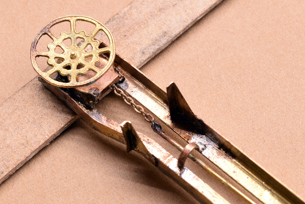
More of the qualities I want to see in the work: tight joints that are clean and free of excess solder.
Jigs Are The Key
An issue with the first hand brake assembly was getting the various brackets aligned with each other. Sloppiness here just screams at the eyes and detracts from the whole build.
I made a new soldering jig out of half-inch MDF for a base and hardboard to hold the parts in place. As hard as it is to believe, this is my first time using MDF for anything. It’s an excellent material for making jigs like this and I wonder why I waited so long to try it. A 2×4 foot panel of half-inch MDF and eight-inch hardboard was less than $20 bucks for both and will keep me supplied for months.
Making such jigs and fixtures has become a favorite part of scratchbuilding for me and I’m always looking for ways to make them better and more versatile. With my increasingly sketchy memory, I’m also careful to label and notate a jig for future reference, so I don’t have to reinvent the process after a long time between uses. Such notes are as valuable as any tool I have.
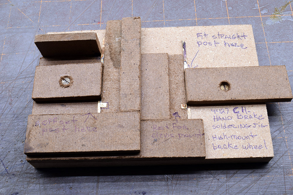
The uprights and brackets are held in place with this jig. A label and instructions on placing the parts serve as an aid to my long-term memory.
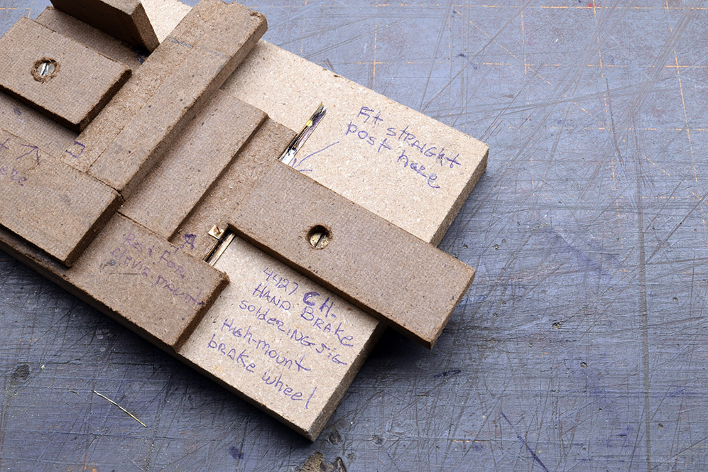
As seen here, the clevis bracket rests on the milled rabbit for soldering. Adding a small stop-block or pin to locate them accurately every time would be a good move.
Each Step In Turn
Even though this is a modern car, there are riveted connections to represent and deal with. Each upright has two rivets to attach it to the bottom cross member on the end cage.
I prefer the crispness of punched rivets from my Northwest Shortline Riveter. Trying to press these rivets after the L angles are bent was unsuccessful because the punch and die were too big to fit the scale five-inch wide flange of the upright. In a pinch, I could have drilled some holes and used plastic rivets from Tichy and I’ve had zero success with rivet decals, so that option is off the table.
My solution was to locate and press the rivets before bending the brass strips into the L shape. This is a case of discovering what the sequence of steps should become for a component. It’s tempting to go for the big moves first but taking care with small details, makes a difference in the quality of the finished part. Another problem in the first build was accurately locating and pressing these rivets. Positioning small pieces of stock on the rivet press is a pain but once again, a simple styrene jig secured with tape to the cross table of the riveting machine provided the accurate alignment for these 0.010” rivets.
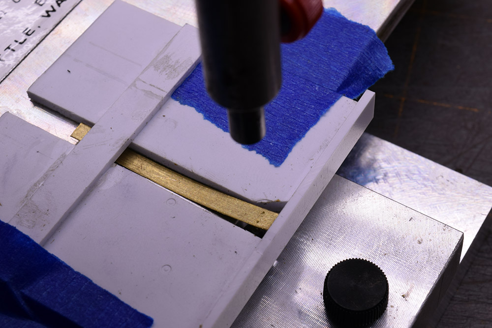
This simple styrene jig aligns the small strip stock for pressing the two rivets on each of the clevis brackets. A similar setup takes care of the rivets for the uprights.
There are rivets for each bracket of the brake step platform and the brackets that hold the brake clevis. These were laid out and pressed in a similar way on both the bracket and flange of each upright. It required some head scratching and close attention to which side of the flange the rivets would face. Once all these parts were ready, soldering them in place was straightforward although one joint on the brake wheel housing gave me fits until I got it solid.
Is It Worth It?
While there’s room for improvement, I’m happier with the second version of this detail. It’s cleaner in terms of construction and more accurate than the first one. I don’t consider the additional time spent on making it as lost or wasted. It’s time invested in developing a skill set that I find valuable and personally meaningful. In that light it’s time well spent for me.
Regards,
Mike
Mike,
I’m always impressed by your solutions. I appreciate you eye for detail and the desire for it to “feel right”. Changing to .008 appears to have made a world of difference in your project.
For a current brass project that I’m working on I will be adding rivets after the brass piece is rolled, formed and soldered together. Once formed I will no longer have the ability to utilize my NWSL Riveter to create the rivet impressions therefore I purchased brass rivets from Scale Hardware and plan to solder them in place. Scale Hardware has a variety of rivet sizes and viewing them under a extreme magnification reveals that they are superbly fabricated. Though drilling that number of very small holes in brass is tedious at best, I think the finished product will be worth it. The rviet “stems are so small that they will need very little heat to solder them inplace. Modeling is my winter go-to hobby and rolling/forming my project and adding the rivets will most likely not occur until after Thanksgiving. I really need to retire so that I have more time to spend modeling.
Great work and thanks again for not only sharing your successes but also your efforts to get there.
Mike
Thanks Mike.
What scale is your project in? I’m aware of Scale Hardware and if I worked in a larger scale, I would send them a ridiculous amount of money. As it is their smallest rivets are too large for what I need in quarter-inch scale, unless I’m missing something.
Mike
Mike,
My project is in S scale. Your comment is true regarding the nut and bolt details BUT their smallest rivet is too small for me to use.
I compiled a “cheat sheet” of rivet head diameters, sprue diameters and the associated clearance drill sizes to mount. It is compiled in both metric and imperial sizes. I would be willing to share it with you if you contact me through email.
Mike
Wow!
Is it worth it? Oh yes.