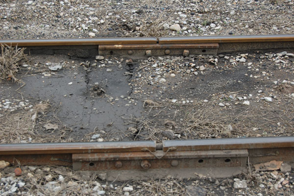
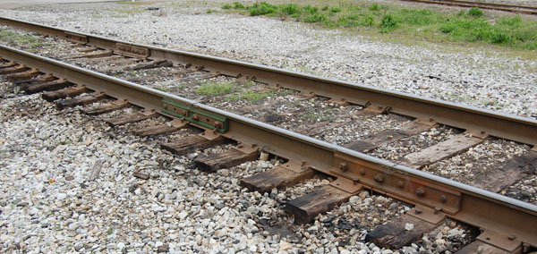
Did you figure out what was different about the trackage in the photo from #12? At least one individual came up with the answer I had in mind. Congrats Trevor!
It might be hard to see in the original photo but, the joint bars are not offset from each other as is typical American practice. I don’t know why the railroad laid things out this way on this particular stretch of track. It seems to be confined to just this short section between the junction turnout and the edge of the highway crossing. Beyond the crossing the joint bars are offset as you would expect them to be. 
It makes for an interesting detail that will certainly generate comments of disapproval from the “experts” who, of course, haven’t added the first joint bar to their own trackage. I admit that I missed this detail myself, or I would have spaced the joint bars on the curved track that leads into the staging cassette differently. I still can make that change, and it’s now on my ever growing list of things to do when there’s nothing else to do on the layout.
I read somewhere that the reason the rail joints were offset is that it made a smoother ride. I read about one Canadian branchline (that well known P87 modeler, Rene’ Gourley uses as his prototype) where things got interesting when a train reached a given speed. The engine and cars tended to develop a bouncing motion due to the flexing of the track at the weaker rail joints. Kind of like riding an inner tube behind a speed boat. Well, maybe not that bad. The other thing that really catches my eyes about this track is how some of the ties are just buried in mud and surrounding debris. The alignment isn’t the best either. Notice too, that there are more than a few bolts missing from the joint bars in the photo above. Could we do this by drilling out a couple of cast on bolt heads on some Right-O-Way joint bars?
Once I noticed these rail joints, I also noticed another oddity on the former NYC main a few steps away.
This short section of rail, if modeled as shown, would also generate the ire of those same visiting experts, who naturally use those oh-so-prototypical folded slip on rail joiners. I’ve seen this application used on the Norfolk Southern mainline at home. I really don’t know why this is done and won’t show any more of my ignorance by guessing. Notice that the joint to the left on the foreground rail is insulated and that there are bond wires on both, indicating something to do with signaling perhaps?
The take-away for me is that prototype track continues to amaze me with its diversity. Don’t let those experts get you down. Especially the ones who write books.
Regards,
Mike

Mike,
Totally missed that one. To be honest, the sectional actually looks somewhat “normal” for secondary trackage. I thought the lack of rail anchors to be interesting, but perhaps they are buried in the muck as well. Excellent story, thanks for the photos and information.
Hi Matt,
Appreciate the comment. Next time I’m down that way I’ll have to look closer myself for rail anchors.
REgards, Mike
Hi Mike,
When the joints are across from each other, the track is called “Box-jointed.” I was told that you would be fired if you laid track like this today, although as I mentioned somewhere, you can still encounter it in other countries; riding it feels a little like riding a kangaroo.
The practice in North America seems to have fallen out of favor around 1900. The Grand Trunk Ry and Canada Atlantic Ry (which was, at 300 miles long, the longest privately owned railway in the world in 1905 – hardly a branch line!) continued to have box-jointed track in the era that I model. Most of the ties at this time weren’t treated, however, and so, the track wouldn’t have lasted much past the Great War.
Loved your book,
Rene’
Hi Rene’
You may not remember but we corresponded many years ago when you were living in London I believe, or somewhere in Great Britain. This would have been in the late ’90s. Your work in P87 was the catalyst for me to make the transition myself, which I did prior to shifting to P48 several years later. I also recall an article of yours in RailModel Journal in the early 2000s about your track modeling of the Canadian Atlantic and its unique boxed joint construction.
The boxed joint work on the I&O branch only continues a short distance past the junction turnout. It transitions to the more common offset pattern after crossing the Federal highway. A mile or two further and the rail weight also changes to a lighter cross section for the rest of the branch.
Welcome to the blog. It’s so very good to hear from you again.
Regards,
Mike Cougill
And now the inspiration runs both ways.
Indeed! Very kind of you to say.
Mike
Mike, Thanks for nudging me into thinking about switching oriented layout theme!
I ran into this website covering a nova scotia branch
that was being taken up in 2005 -2010. Shows very detailed switching moves in New Mina NS. Also has a lot of details on track.
http://ns1763.ca/rail/whr-minas-june15.html
Hi JR,
Welcome to the blog and you’re very welcome. As a courtesy to everyone, I ask that folks sign their comments.
Regards,
Mike
Hi Mike,
Me again. I’ve been trying to figure out the proper tie spacing around joints. It seems like nowadays, they try to arrange the ties so that the joint is between two ties. I’ve been reviewing all my photos of track for the Canada Atlantic, and it looks like they were either indifferent, or aimed to place a tie directly under the joint. Have you noticed any change in best practices in your historical research?
Cheers,
Rene’
Hi Rene’
Always good to hear from you.
I haven’t done that much research into tie spacing or location at track joints. I suspect that as trains became heavier and overall speeds increased, the tie spacing and placement at rail joints were adjusted accordingly. Having said that, I was quite surprised at how lightweight the rails on mainline trackage still were and that the use of tieplates wasn’t even close to universal. That didn’t come until after the turn of the twentieth century.
This is speculation on my part, but I would think that prior to the American Civil War, practices were less stringent than afterwards. My practice is, when in doubt, follow the example of the railroad you’re modeling. Sorry I couldn’t be of greater help.
Regards,
Mike
Thanks Mike. You are so lucky to be able to wander down to the track and see what is there today! It doesn’t look like anyone went to the trouble (and expense) of taking any nice close-up shots of track on the Canada Atlantic at all! Unbelievable, I know. Keep up the great modeling. Rene
The modern era does have its perks.
Regards,
Mike