Using Joint Bars In Track Modeling
A prime reason I enjoy P48 so much is the opportunity it affords me to model the details I love. That potential is what drew me to quarter-inch scale and there was never any hesitation in my decision to go all in with track modeling.
Details like joint bars set the tone for museum quality track. We take them for granted when we’re looking at full-sized track but just accept their absence on a layout or in model photos.
Joint bars are one of those sneaky little items that will surprise you. You might think you can add them here and there in high profile areas but once you start, there’s no stopping because you will miss them in the rest of the scene.
They are also sneaky with regard to the quantity needed, even on a small layout like my former Indiana & Whitewater. Placing a pair every 39-scale feet (or 9-3/4”), the number of those little packages adds up fast, unless you have a source to purchase them in bulk.
At the time I built my track I purchased all my details from Right O Way Products for the sake of consistency, using both four-hole for code 100 rail and six-hole for code 125. The number of holes a joint bar has is mainly determined by rail weight. I also used insulated joint bars around turnout frogs that have a plastic spacer for creating electrical gaps much like the ancient slip on plastic rail joiners from decades past.
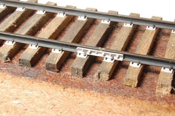
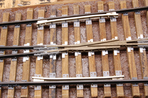
I used ROW’s glue on joint bars. After determining the locations, I glued one to each side of the rail with a dab of gel CA and did the same for the insulated bars on the heel and toe of the switch frogs (photos above and below). I waited until after the rail was spiked in place and usually had to pull and reset a couple of spikes to place the bars. Initially I was happy at this point but as I studied track more closely and learned more about prototype practices, I went back and refined things.
At first I didn’t cut or notch the railhead, but went back later and did so with a razor saw. It helped visually, especially in close-up photos, where the continuous rail at the joint stood out like a sore thumb. As for the wheel sound, not so much, which was fine. I always thought it a bit gimmicky anyway.
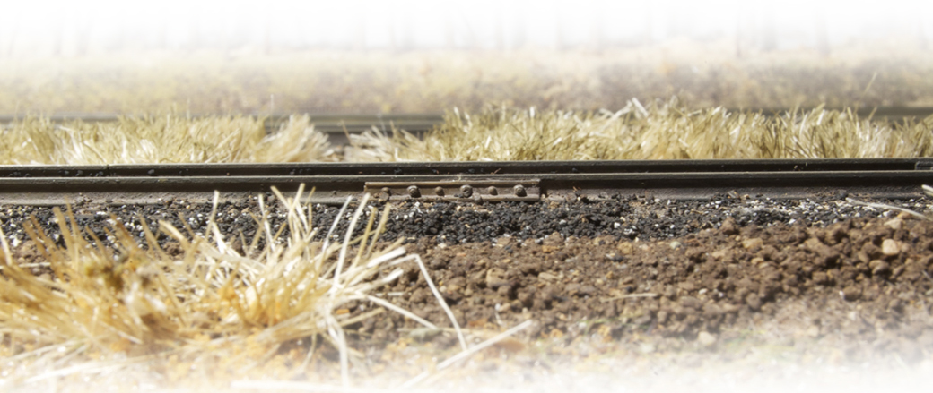
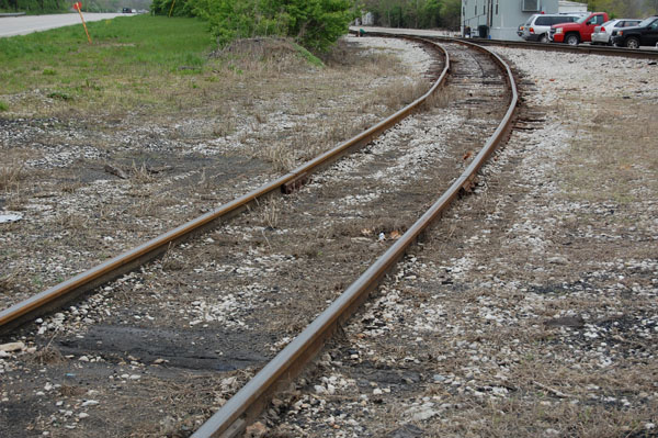
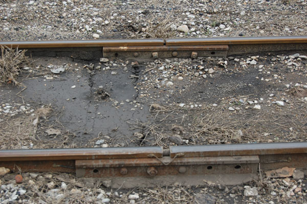
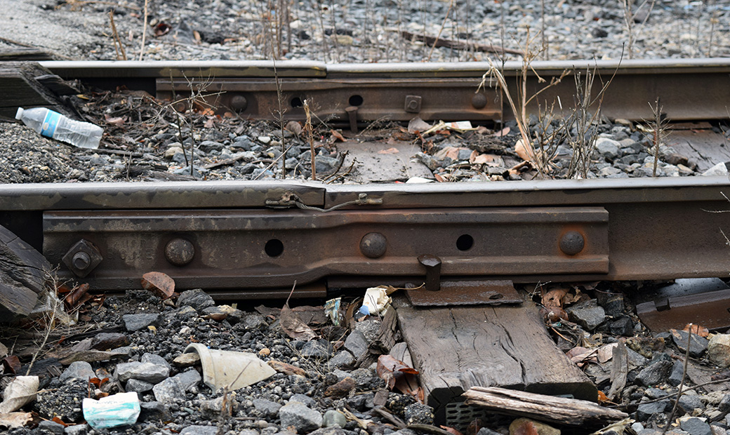
On the prototype, rail joints are usually offset from each other. Typical practice is to offset opposing joints by ten ties, although I imagine this spacing could vary from company to company. While offsetting joints is a common practice, there are exceptions such as this section on the Indiana & Ohio at Valley Junction. Here the rail joints are opposite each other for a short distance and revert to an offset spacing on the other side of the crossing for US 50 (photos below).
My understanding is that staggering the rail joints strengthens the track structure and provides a smoother ride. One can imagine the pounding and hopping qualities at speed over rail joints like the one in the close-up image from Valley.
Another practice I’ve become aware of is the re-use of old rail on secondary tracks. Jointed rail suffers the most wear at each end, where the railhead gets rounded over from the flex and pounding at the joint. These worn areas are trimmed off leaving shorter lengths of perfectly good rail that is used as repair infills. Depending on the type of service this relay (?) rail might match existing conditions or not and can be of any length as needed. Storage tracks in older yards may be a hodge-podge of rail sizes as one example of this practice.

I never modeled this on the layout due to my ignorance but plan to on future projects. As I continue my interest in track modeling, I’m learning there is far more than meets the eye.
Special Purposes
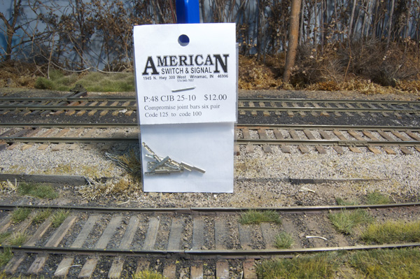
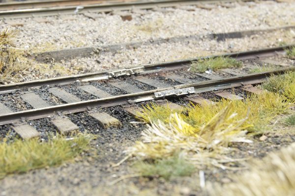
Special purpose joint bars come in several variations depending on the needs of the situation. A common one is a compromise joint between rails of different weight. In Richmond several grade crossings feature heavier rail through the crossing with lighter weight rail on either side. I’m guessing the heavier rail withstands the pounding from vehicle traffic better, lessoning the maintenance costs and replacement schedule. On the layout, I used compromise bars from American Switch & Signal (now available from Right O Way) on the Pole Track where it changed from code 125 to code 100. These added a nice touch of realism that lifted the scene from the ordinary.
The prototype also uses insulated joint bars to isolate sections of track for signaling purposes. These special bars are easy to spot once you recognize them. I’m not aware of any commercial products for these but I could be mistaken about that.
Modeling track at this level is extremely satisfying for me. It isn’t everyone’s cup of tea and that’s fine. It’s a choice one makes. I’ve been chasing this dream for over ten years and still have much to learn. There are modelers like Jim Lincoln (a railroad professional), whose understanding of track far exceeds mine. The bottom line is I’m always learning and that’s the point of the craft for me. As for the products mentioned, there are no affiliate arrangements involved. I mention them because I use them.
Your mileage is bound to vary.
Regards,
Mike
Hey Mike,
Thank you for the great read! Guess I’m a little prejudiced, huh? My own self interests aside, your article is great. Thank you, again,
A little prejudiced? Well, so am I 😉 Thank you Jay for carrying on Lou’s tradition of fine service and product lines. P48 would be poorer without both.
Mike
I should also mention Jim Lincoln’s Shapeways Store that features a number of track details that will compliment Right O Ways line. there is plenty of variety in full size track and having a wide range of details to pick from is a good thing.
Link as follows: https://www.shapeways.com/shops/batsbyjim?li=pb
Mike
Mike,
Someone once told me that joints that are opposite is called “box-jointed”. They went on to say that you would be fired for it!
Not so in England, where it seems to have been the norm. When I lived in Henley, the branch was still 60’ box-jointed rail. It felt a little like riding a kangaroo.
The other neat thing about modelling track is that practices changed (slowly) over time. So, you can help fix the timeframe of your model by keeping the details right. Of course, only track-nerds like us would know…
Thanks for the fun read
Rene
Hi Rene,
I figured there was a name for that but had no idea what it was. In addition as smaller railroads were consolidated into larger systems, the track structure reflected the different practices until maintenance or a major upgrade was needed. As you suggested a given era can reflect a wide range of materials and standards. Good to hear form you again.
Cheers,
Mike
Another detail often not modeled is the metal pieces on the tie ends. I’m not sure what the name is, but they are hammered/stapled to the tie ends to prevent the tie from splitting.
As a fellow track nerd, my plan is to start slowly super detailing the track around turnouts, and then as funds are found expand the details outward.
Another detail found on tracks is isolated rail joints. These are used around grade crossings and signals. Often regular track joints (non welded rail) will have a small jumper wire connecting the two pieces if inside a grade crossing circuit or in signaled track. One of the benefits of modeling yard trackage/non-signaled track you only have to add the jumper wires at grade crossing circuits.
These details add up in any scale. I’m slowly working on designing these parts for 1/29 track (code 215 rail) as most of the track details are non existent.
Craig
Hi Craig,
I think I have images of isolated rail joints but am not certain so I didn’t post any. I can only imagine the difficulties of working in a very niche scale like 1/29.
Mike