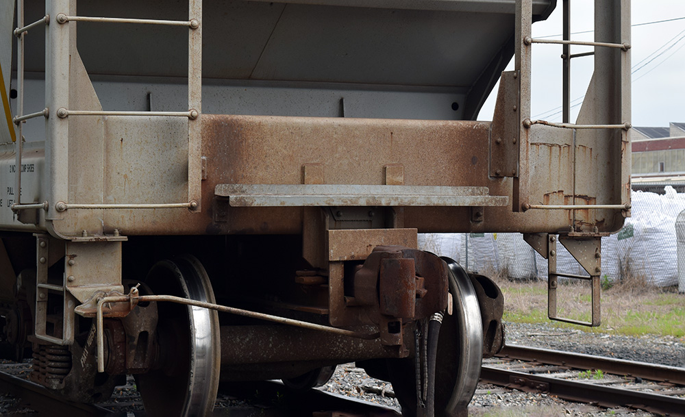
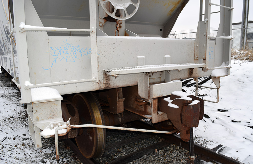
Referring again to the hopper car that was the subject of my sketches in the last post, I had questions about how a few details were resolved on the car. I’ve been waiting for an opportunity to shoot more images and satisfy my curiosity.
I found a subject car at a convenient location and set about shooting the images. Looking at them at home, I noticed a difference in the corner posts from the previous car. This anomaly sparked a number of new questions.


I’m not a freight car expert so I can’t offer anything concrete about the difference in the corner post design between the cars. Is the design on the original car a modification, a repair? Is one of them a subclass of the other? Which one is normal and which is the outlier? At this point, I simply don’t have a clue.
The wind chill was bone numbing cold, so I didn’t linger long enough to look for a build date or other clues on the second car. For now, the search continues fueled by a new round of questions.
I never would have noticed this without the thorough study my sketches required. As crude as my drawing are, they helped me see the car more clearly. Once I see something like this, it’s a hard detail to ignore when planning the model. Obviously, there is more research to do and further questions to answer. A cursory look at other cars suggests a few answers but nothing firm yet. This is what keeps the craft fresh for me.
Regards,
Mike
I used to think modellers who could just go out and look at the prototype were lucky. Now I’m not so sure.
It’s all part of the fun isn’t it? The beauty is I could model either version and it would be correct for that car.
Mike
What I find interesting about the observation, and it aligns with something that I’ve noticed in my observations of railroad equipment and as a designer working for a few architectural metals fabrication shops over the years, is that it underscores and humanizes the reality that each piece of railroad equipment is hand-built. We are craftsman duplicating the work of craftsman (or, in plenty of cases, somebody that’s just trying to earn a paycheck).
Once we get to the level of scrstchbuilding in brass, we’re no longer just duplicating the aesthetics of this equipment – we’re duplicating, in miniature, many of the steps of fabrication. Yes, we’re soldering instead of welding, but the metalwork is identical: we buy structural shapes (sheet, bar stock, rod, tube, angle bar, beams); we saw, shear, punch, drill, fold, and bend; we solder (our version of weld), screw, glue, and use alignment tabs. We are learning, through studying and through recreating, how the prototype is built.
Sometimes maybe we’re running a little low on materials and use something on-hand or, perhaps as we assemble something, we notice a better or more efficient way we could do it next time. It’s the same for the folks building the real thing.
Most people think of mass production as cranking out identical units based on automated production steps. While this is true for things like cars or plastic railroad models, this isn’t the case for something like railroad equilment.
Many of the components will indeed be identical, fabricated with automated techniques (like CNC laser-cut plate and CNC folded parts); however, many parts are still handmade such as the ladder mounting brackets in Mike’s post. Pieces like that are hand cut, probably in a large group, using a stop to cut duplicate lengths.
It’s likely that an engineering change was made and a drawing revision sent out changing from one style to the next for some reason; maybe one version cost a few bucks less because it removes a step or uses a component being used on other equipment, improving efficiency.
But it’s also possible that some material or other was running low and, knowing that this was a change that would not affect the overall integrity of the railcar, the fabricators in the shop made due with what they had on hand to get the job done and hit their deadline.
The important takeaways are 1) to truly create an accurate model, you need as much documentation on that exact subject as possible, and 2) the more we improve our modeling skills and strive to improve our observations of the prototype, the more we will notice these little details which add nuance to our appreciation and understanding of said prototype and to the actions of professional railroaders (and fabricators).
Chris those are solid observations. The more closely I study actual equipment, the more I realize how individual it is. Not only in terms of design variations but also from wear and abuse from service time, weathering, paint fade, rust chips and streaking, repairs in the field and so on. A freight car can be as unique as a person in this light. It all strengthens my desire to capture this uniqueness in the model. Thanks for commenting.
Mike