I want to thank everyone for their comments and encouragement from the previous post. I truly appreciate knowing when a topic is helpful for you all. Let’s get to it.
Every build is a process: a series of steps taken in a certain order. As fundamental as that seems, it’s amazing how often one can ignore that truth and make the work harder than it has to be.
I’ve reached the point where I wanted to solder the bolsters in place but, there are other steps that need to be done first.
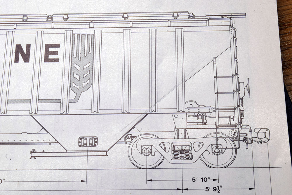
A close review of the drawing from the December 1983 Mainline Modeler magazine that I’m working from shows that the slope sheet on each end has two different angles to it. It’s a subtle change of only five degrees or so, however it is noticeable on the car (Photo 1). One of my goals is to raise the overall level of quality in the work via better fitting joints, cleaner edges and more precise dimensions on each part. The slope sheets are 0.032″ thick stock. Just trying to bend them by hand wouldn’t produce a clean result. Furthermore, rendering this bend before attaching more delicate assemblies is just common sense.
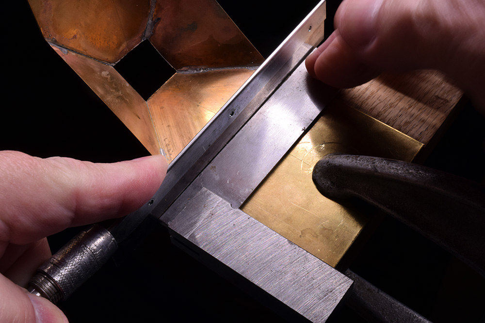
I marked the position of the bend with a scribed line on the inside of the slope sheet, and then clamped the model to the workbench. (See this post.) Using a small square as a guide, I made a shallow cut with a fine toothed razor saw along the layout line to create a notch in the material (Photo 2). I exercised care in doing this as it was easy to go too far even though the brass is thick. Once I had an initial cut to guide the tool, I also could have used a small file to open the notch further but didn’t do this. (Because I didn’t think of it until writing this text.)
The notch reduces the thickness of the end sheet at that spot, making it easier to get a cleaner bend. I carefully did this by hand being very aware to not overwork the material to the point where it would fracture and break. I didn’t heat the brass to anneal it because there are soldered joints close by that I didn’t want to risk coming loose.


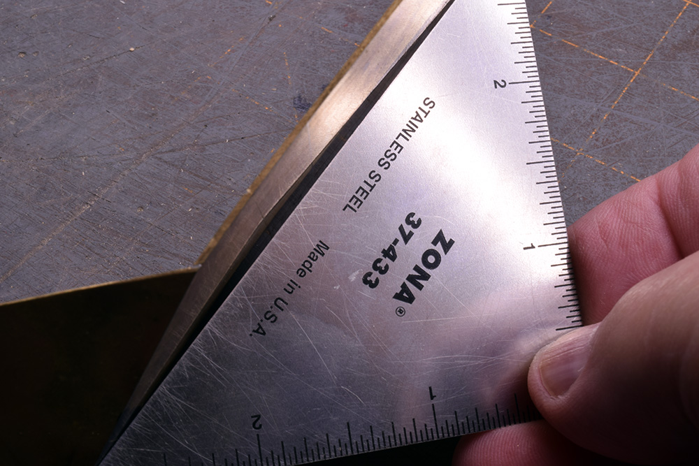
Photo 2. Clamping the model to the bench allows for a precise cut to notch the thick sheet for easier bending. Photo 3, below shows the amount of offset, about five degrees.

Had I thought ahead, I could have done this step before soldering the slope sheets together. It would have been simpler and that’s a lesson learned for the next project. In addition to the bend, there are vertical sheets on both ends to consider along with the brake appliances, piping and other associated parts on the B end of the car. These components will be both thick and thin materials and all have an installation sequence I need to think through.
I’ve also thought about the car body itself. I plan to make the substructure from 0.080″ styrene laminated with 0.005″ brass sheet for the finished sides. The sequence of any and all soldered parts on the ends needs to be considered carefully as the heat from such operations will likely damage the styrene if I get ahead of myself.
It all sounds complicated and intimidating and it can be at first. Truthfully, the planning and analysis involved is as enjoyable and satisfying for me as the execution. Each build is unique, in that I’m mostly flying blind and making it up as I go. Experience has taught me how easy it is to rush the work and be driven into a corner you can’t back out of. It’s always a hard but valuable lesson to learn and that’s why the work goes slowly. That’s fine as I’m in no hurry.
Regards,
Mike
Mike,
I always enjoy your blogs. They’re insightful and make me think about how I approach my projects and the methods that I employ. Usually, they are similar, but as expected, not identical.
For work holding clamps I use Kant Twist clamps. They hold the work securely, can also be used as grounding clamps, seldom “mark” the work surface and unlike “c” clamps, they don’t rotate. They’re a parallel acting clamp. I had attempted to attach an image, but it appears I can’t in this blog but they’re easy to find on the internet. I have a variety of sizes and have used a Kant Twist clamp to lock in place another Kant Twist clamp that is holding my work piece.
Hi Mike,
I’ve seen that clamp before but didn’t know what it was called. With the right sizes, it looks useful for modeling. Here is a link to an Amazon page for people who don’t know what kind of clamp it is. (No affiliation whatsoever with this link, just for people’s own information.) -Mike