Hand laying turnouts isn’t hard. Getting over your reluctance and internal fear is the hardest part. Once that hurdle is out of the way actually doing the work is simple. I learned how to hand lay turnouts when I was a teenager. Back in the dark ages, the options were make do with ready made Nos. 4-6 or do it yourself. Numerous articles were readily available covering a range of techniques for hinging the points and fabricating the frogs. Seems everyone had their own spin on the subject, since hand laying track was more common in those days.
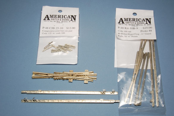
P48 and other 1:48 modelers have an abundance of excellent products to pick from. American Switch and Signal has made the task simple for P48 with a line of outstanding castings and kits for a wide range of frog angles and sizes in both standard and narrow gauges (photo below). Right -O-Way covers the tieplates, joint bars and other details and, Jim Harper has resurrected his line of switchpoint and frog castings. The times are good in quarter-inch scale with more suppliers bringing products to market. Google will be your friend here.
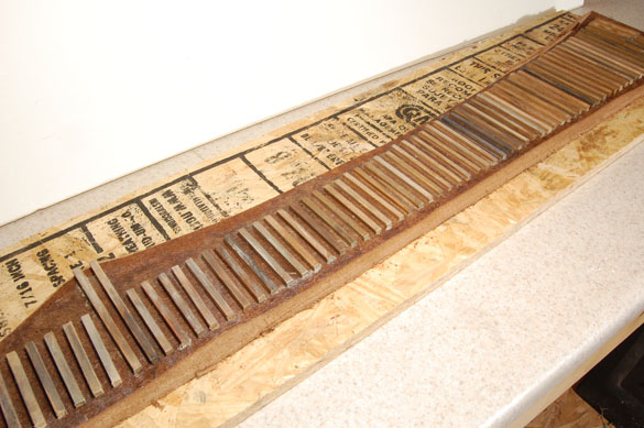
To scratchbuild a turnout, I start with the tie layout. Timber schedules for the number and layout of ties for various sizes of turnouts aren’t hard to find. I believe the NMRA has them in their standards sheets, Numerous railroad historical societies have reprinted specific MoW manuals and other resources are out there. Mr Google will help here also.
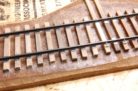
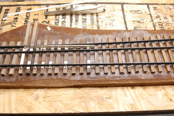
If you’re following a specific railroad and can safely photograph their trackage, do so. That will be your best guide to getting the details right. My prototype was once a New York Central branch built to light duty standards, which is what I’m reproducing for this demo/display turnout. Once the ties were ready, I start with the stock rails. I spiked them in place and inserted enough tieplates to keep things moving along at this stage. On the layout I would drill a hole for feeder wires, which are soldered to the underside of each rail prior to spiking them in place.
The gauge plates for the branch are light duty (the styrene strip on the first long headblock tie). I used 0.156″ wide by 0.020″ thick styrene to match the thickness of the tieplates. The slide plates under the points are the same stock and I could have done a better job of cutting and measuring them. The rail braces on the outside of the stock rails are castings from Right-O-Way. I aligned the straight stock rail first, adding enough spikes and tieplates to fix it in place. I’ll fill in the rest of them later after the other rails have been added.
Each turnout has a specific lead measurement, or the distance from the tip of the switchpoint to the tip of the frog. In the case of a No.10 it is 78 feet. I marked this with a pencil line on the tie next to the point of the frog casting. If this was on a layout, now is the time to drill a hole through the baseboard for a wire to power and switch the polarity of the frog. I didn’t do this here since this is only a display piece for shows. For now, I just temporarily spiked the frog in place.
Once the frog is located, you can gauge the diverging stock rail accordingly and establish the curve it requires. I let the rail form its own natural curve between the frog and point areas. Where the switchpoint meets the diverging rail, I make an ever-so-slight bend in the stock rail. Don’t get carried away with this. Make it just enough for the switchpoint to nestle into. Add a few tieplates and enough spikes to hold the diverging rail in place. Don’t get carried away with adding spikes and tieplates around the points yet. There is still work to do there.
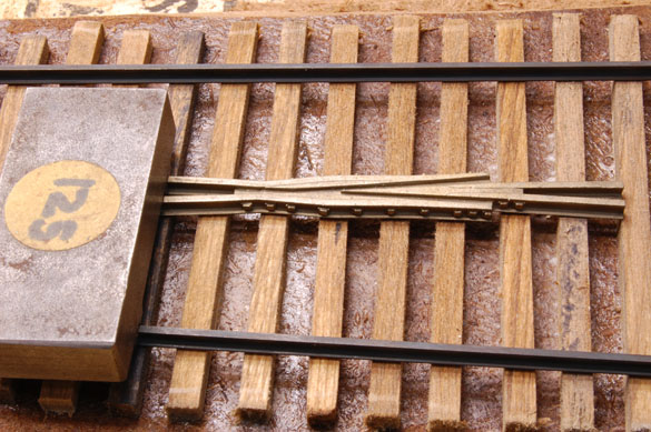
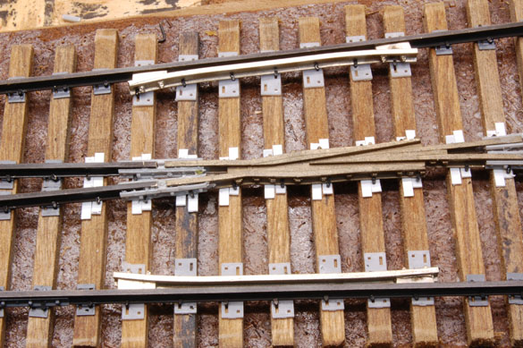
I placed the point casting where it needed to go and measured the length of the closure rail from the frog to the heel of the points and marked the rail for cutting as seen above. Do the same for the other route. Commercial castings like these remove the hard work of building turnouts. You don’t have to file the points or the angles of the frog, nor do you have to bend the wing rails and solder it all together. The casting do that work and are much more detailed as well. All I’m doing is cutting rail to length and spiking it down.
There are numerous ways to handle the connection of the points to the closure rails. On my layout, I soldered one side of the cast on rail joiner to each closure rail, using it as a hinge. Doubters have expressed that the bending forces will eventually fracture the metal. I however, use hand throws and don’t operate that frequently. If something breaks, it breaks and I’ll deal with it then. If this is a concern, or you plan to use mechanical switch motors, you can solder a jumper wire and leave the actual hinge point free as shown above. The jumper is simply a piece of soft brass wire either 0.015″ or 0.019.” I don’t recall the exact size and it doesn’t matter. It is bent into shape and set in place with some paste flux prior to soldering the ends. However you choose to handle this connection be certain you have a solid electrical path. I don’t rely on the switchpoints for electrical contact.Instead I solder a #18 gauge solid wire feeder to every length of rail on the layout, all connected to #10AWG bus wires via suitcase connectors to ensure a bulletproof electrical pathway.
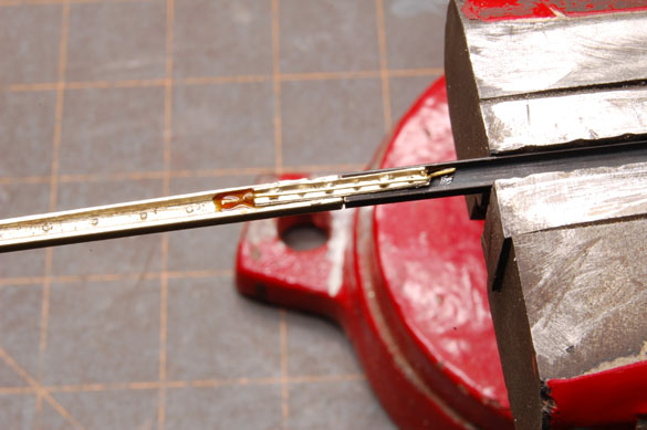
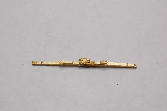
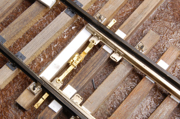
To connect the points, I used ROW parts. These are two-piece brass castings that need to be trimmed to length and insulated. I spaced the open point with a piece of 0.080″ styrene to give the four inch spacing of the prototype. The two halves of the casting are fitted and marked for cutting. You’re instructed to wrap a piece of paper around the cut end of one half and secure it with CA or Walthers’ Goo or similar adhesive. I used gel type CA (photo below).
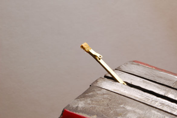
The two halves are assembled and fitted to the points again. I drilled out the holes in the head rod and clips on the switchpoints to accept Micro Engineering’s micro-spikes to pin them together. (Photos following.)
Caboose Industries ground throws have the right amount of throw for P48 and they are also close to scale in size. I nip off the excess portions of the tongue and drill a hole in the end for the brass wire throw rod. The cylinder cast onto the head rod is hollow and the ends are easily drilled out for inserting the throw rod. I use more gel CA on these joints. One could solder the brass wire to the cylinder, but do so before securing the two halves of the head rod with CA. The heat will loosen the connection if done afterwards. In the photo below, I added the second rod or back rod. I cut off the cast on cylinder as it isn’t required.
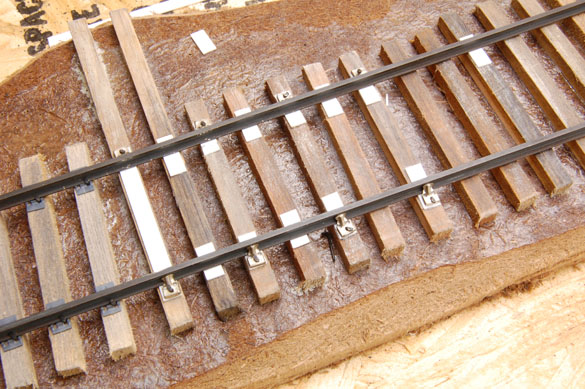
The completed frog is shown below. In the past I used the longer slide plates from Right-O-Way (seen under the guardrails) under the frog castings. For this demo I used 0.020″ x 0.100″styrene strips to represent the offset tieplates. They came out so well, I wished I had done this on the layout. I could retrofit them some day when I have nothing else to do. You can also see that I’ve added the rest of the spikes and tieplates, guardrails and other details as needed. The turnout is essentially complete at this stage.
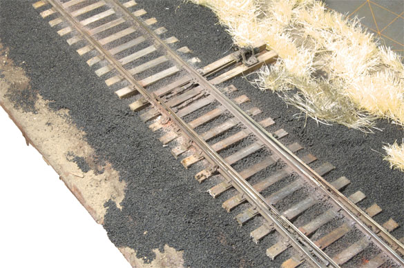
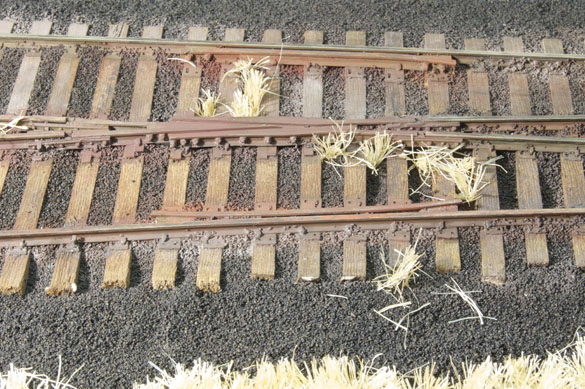
Final painting, weathering, ballast and detailing results in the finished track model seen above. The techniques aren’t hard to learn or master. Getting over your inhibitions is the hardest part. Trust me, you can do this too. For much more advice and step-by-step instructions on modeling track like this, check out a copy of our book Detailing Track. You can purchase your copy here. Questions or comments, let me hear from you.
Regards,
Mike
Related posts:
On Track: Modeling the details
The Details Are in The Turnouts


I have a couple of observations: all commercial turnouts and articles about building your own turnouts (including Fast Track jigs)require grinding off the flanges on the stock rails. In real life this would severly weaken the stock rail.
I have studied actual turnouts and it appears that the point rail flanges are ground off on the side facing the stock rail and are mounted on a plate in such a way that the point rail base slides over the stock rail flange and fits inside the web of the stock rail and tight againt it.
You will notice that even in this series of photos the stock rail flanges are ground off and point rail is ground on the inside edge so it is tight against the stock rail at the top surface of both rails. In this case the wheels will strike the point and cause a bump.
In addition in real life, the leading top surface of the point rail is ground down below the mating stock rail so that the car wheel do not contact it. The grind slopes up from the point to the top of the rail. That way the wheel gradually transfers to the full point rail. This also aids fitting the point inside the web of the stock rail.
Mike,
What is the approximate cost of building the turnout described in this post? I ask because I want to compare that answer against my calculated costs of using FastTracks product line.
Thanks,
-GmG-
You make excellent points (no pun). I don’t file off the flange on the inside of my stock rails because the switchpoint castings make this unnecessary. I do clean up the tip of the points for a smoother transition.
I want to inform folks that we’re having a problem with the blog. We hope to have it fixed by Friday. Until then we’re very limited in what we can do in response to comments. We can’t approve new comments until then. Sorry for the inconvenience and headaches. We’re on it though.
Regards,
Mike
Hi Gary,
Roughly, the costs are 45-55 dollars when all the extra detail parts, tie material, spikes, rail, etc. are factored in. Might sound expensive, but consider what you’re getting in terms of quality and detail.
I’d like to request that all folks sign their comments.
Regards,
Mike
Looks great. I love the details. I’m building some highly detailed HO turnouts now, but every time I see great looking O track I want to scale up 🙂
Greg Amer
Hi Greg,
Appreciate the comment. I’ve visited your own blog and enjoyed the approach you’re taking.
Regards,
Mike